
XL-20
-
Detail
Product Description
1. Product Overview
The full name of the XL distribution box is XL-type Low-Voltage Power Distribution Box. It adopts domestically independently designed components, featuring a compact structure, convenient maintenance, and flexible combination of circuit schemes. In addition to air circuit breakers (for short-circuit protection), the distribution box is also equipped with contactors and thermal relays. Operational buttons, indicator lights, and other components can be installed on the front door of the box.
This equipment complies with the International Electrotechnical Commission (IEC) standard IEC 439-1 "Low-Voltage Switchgear and Controlgear Assemblies", China’s national standard GB 7251-1997 "Low-Voltage Switchgear and Controlgear Assemblies", the standard JB/T 9661-1999 (jointly issued by China’s national standards authority and the China Machinery Industry Federation), as well as the requirements of the CCC (China Compulsory Certification) certified by CQC (China Quality Certification Center).
2. Product Application
The XL series AC low-voltage distribution box is used for power distribution and lighting in 3-phase 4-wire or 5-wire low-voltage distribution systems with an AC frequency of 50Hz and a rated voltage of 380V or 660V.
Scope of Application
This equipment is suitable for power plants, substations, large-scale buildings, high-rise buildings, airports, hospitals, theaters, stadiums, ports, underground facilities, industrial and mining enterprises, etc.
The XL-type distribution box is used for power distribution in 3-phase 4-wire or 3-phase 5-wire systems with an AC voltage of 500V or below.
It is an indoor installation, designed to be wall-mounted, with maintenance performed from the front of the panel.
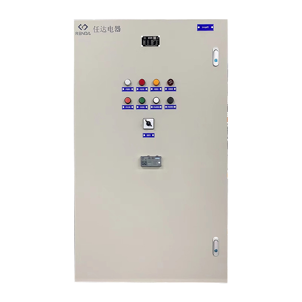
Product Features
The XL-type distribution box is of a closed design, with its outer casing made of bent steel plates. The operating handle of the knife-fuse combination switch is located on the upper part of the right front column of the box, which can be used for power source switching. A voltmeter is installed on the front of the distribution box to indicate the voltage of the busbar. The front of the distribution box is equipped with a door; when the door is opened, all internal equipment of the box is exposed, facilitating maintenance and service. This distribution box adopts domestically independently designed components, featuring a compact structure, convenient maintenance, and flexible combination of circuit schemes. In addition to air circuit breakers and fuses for short-circuit protection, the distribution box is also equipped with contactors and thermal relays, and operational buttons and indicator lights can be installed on the front door.
-
It is divided into two types: the standard type with a box height of 1600mm or 1700mm, which is installed independently, and can have wire inlet/outlet holes opened at the top as required; the type with a box height of 1800mm is equipped with a top busbar, and the top of the box is fitted with a detachable cover plate to facilitate the installation and disassembly of the busbar.
-
The box body uses section steel as the frame; the door panel, side sealing plates, and rear sealing plate are all detachable. The mounting plate and side beams are adjustable, enabling flexible and convenient installation and maintenance, along with a compact structure and good versatility.
-
Precision-cast adjustable door hinges are adopted, allowing the door to open to an angle of more than 135 degrees.
-
After the components are installed, the mounting brackets inside the box can be adjusted as a whole.
-
Wire inlet/outlet can be installed according to different operating environments, featuring good versatility, and multiple units can be used in combination.
Technical Parameters
-
Knife-Fuse Combination Switch
Model Rated
Current (A)
Fuse Element Rated Current (A)
HR3—100/34
100
30, 40, 50, 60, 80, 100
HR3—200/34
200
80, 100, 120, 150, 200
HR3—400/34
400
150, 200, 250, 300, 350, 400
HR3—600/34
600
350, 400, 450, 500, 550, 600
-
Air Circuit Breaker
Model Rated
Current (A)
Fuse Element Rated Current (A)
DZ20—100
100
20, 25, 32, 40, 50, 60, 80, 100
DZ20—160
160
20, 25, 30, 40, 50, 60, 80, 100, 125, 160
DZ20—225
225
125, 160, 180, 200, 225
DZ20—250
250
125, 160, 180, 200, 225, 250
-
Current Transformer
Model
Rated Current (A)
Secondary Current (A)
LM—0.5
75, 100, 150, 200, 300, 600
5
-
Fuse
Model
Fuse Body Rated Current (A) of Fuse
RL1—15
15
2, 4, 5, 6, 10, 51
RL1—60
60
20, 25, 30, 35, 40, 50, 60
RL0—100
100
30, 40, 50, 60, 80, 100
RL0—200
200
80, 100, 120, 150, 200
RL0—400
400
150, 200, 250, 300, 350, 400
-
AC Contactor
Model
Rated Current (A)
Pull-in Coil Voltage (V)
GJ20—10
10
Alternating Current
110/220/380
GJ20—25
25
GJ20—40
40
GJ20—63
63
GJ20—100
100
GJ20—160
160
-
Instrument
Model
Name
Unit
Range
Remarks
6L2-A
Ammeter
A
5,10,15
Direct connection
5,10,15,20,30,50,75,100,150,200
Connected via current transformer
(secondary coil current: 5A)
6L2-V
Voltmeter
V
250,300,450
Direct connection
-
-
Customer ReviewsNo comments